Vt Commodore Ignition Wiring Diagram, Complete Wiring Diagrams For Holden Commodore VT, VX, VY, VZ, VE, VF, 5.36 MB, 03:54, 32,796, John Amahle, 2018-08-01T19:37:41.000000Z, 19, Vt Commodore Ignition Wiring Diagram, to-ja-to-ty-to-my-to-nasz-swiat.blogspot.com, 1272 x 1800, jpeg, bcm pcm 12j swiat nasz, 20, vt-commodore-ignition-wiring-diagram, Anime Arts
Elk m1 wiring diagram. By admin | february 5, 2018. M1 diagrams elk products product review gold cross platform control system m1ez8 controls 6 tips for better installations with the swb28 enclosure jetpak installation guide controlling window treatments users manual programming page of biscuit joiner m1g user manualsonline com. Set jp1 to 'normal'.
Out 1 †† 4. Is the wiring diagram between the items correct ? Jan 25, 2012 #2 i recently installed an elk m1 myself, so i'm still learning, but here are my thoughts: First, you can power up the elk m1 without any worries. If the resisters are not in place, you will just get zone warnings. This is my elk m1 connections diagram done in visio and exported as a jpeg. Search for jobs related to elk m1 wiring diagram or hire on the world's largest freelancing marketplace with 20m+ jobs. It's free to sign up and bid on jobs. Brown optional programmable output from keypad keypad 1
Elk M1 Gold Connection Help - !!..DIY Installers..!! - Security Installer Community
Product Review - Elk Products - M1 Gold Cross Platform Control System
New ELK M1 planning - New home - Page 4 - Home Security - CocoonTech.com
ELK-M1_Line_Level_Output.gif (774×488) | Line level, Capacitors, System

Elk m1g drip irrigation control - Home Automation - CocoonTech.com

Don't Get Washed Away By Water Leaks - ELK Products

Elk ELK-M1KP2 Keypad Operation & user’s manual PDF View/Download, Page # 3

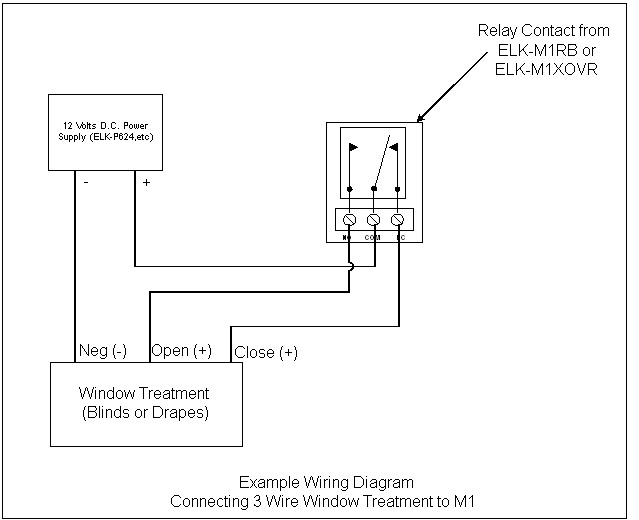
Controlling Window Treatments - ELK Products

Controlling Window Treatments - ELK Products

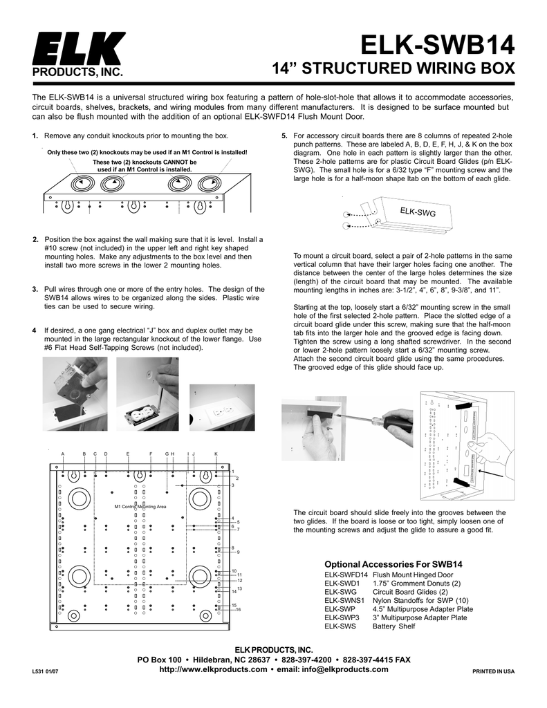
ELK-SWB14
