Vt Commodore Ignition Wiring Diagram, Complete Wiring Diagrams For Holden Commodore VT, VX, VY, VZ, VE, VF, 5.36 MB, 03:54, 32,796, John Amahle, 2018-08-01T19:37:41.000000Z, 19, Vt Commodore Ignition Wiring Diagram, to-ja-to-ty-to-my-to-nasz-swiat.blogspot.com, 1272 x 1800, jpeg, bcm pcm 12j swiat nasz, 20, vt-commodore-ignition-wiring-diagram, Anime Arts
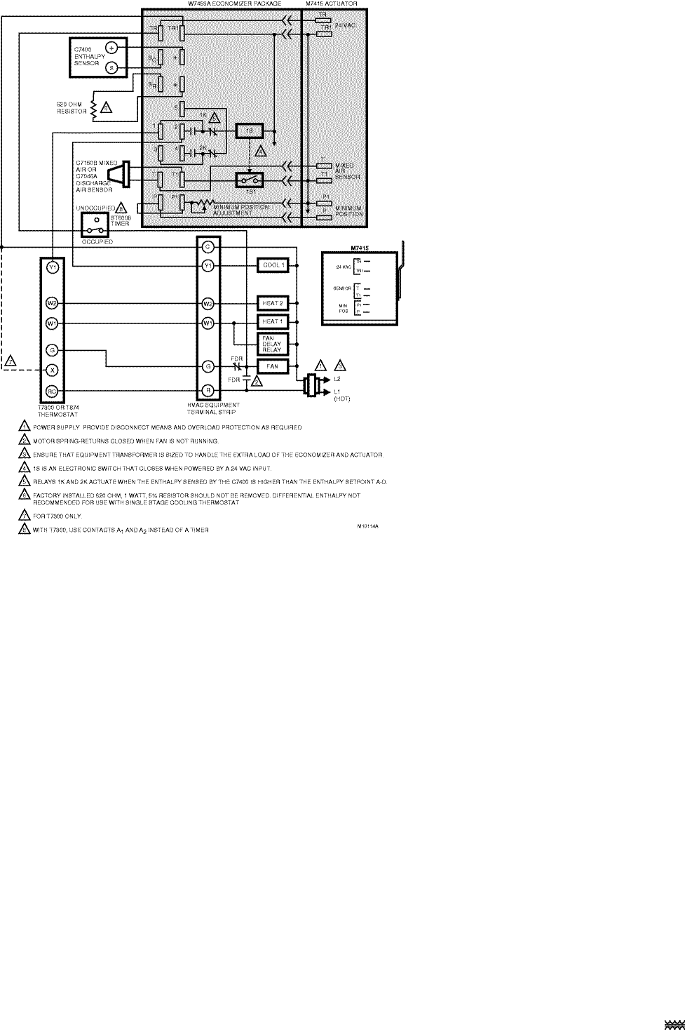
Economizer wiring diagram direct plug into side of low voltage box balanced climate operation. And connect wire from vent plug pin #1 to high speed solenoid wire. The economizer installation requires an additional two stage cooling thermostat in place of the normal. Single stage cooling thermostat.
See figure 5 on page 8 for thermostat options. Operation the purpose of the economizer is to use outdoor air for cooling, whenever possible, to reduce compressor operation. Power at the n terminal determines the occupied/unoccupied setting: • 24 vac (occupied). Economizer wiring diagram black balanced climate operation. See economizer and unit installation instructions. Depending on economizer size step 5: Affix d1 economizer wiring diagram section to inside of compressor access panel. Position diagram to the right of “c” control wiring diagram section.
Carrier Economizer Wiring Diagram
Carrier Economizer Wiring Diagram

Carrier Economizer Wiring Diagram
Carrier Economizer Wiring Diagram

Carrier Economizer Wiring Diagram
Carrier Economizer Wiring Diagram

Carrier Economizer Wiring Diagram
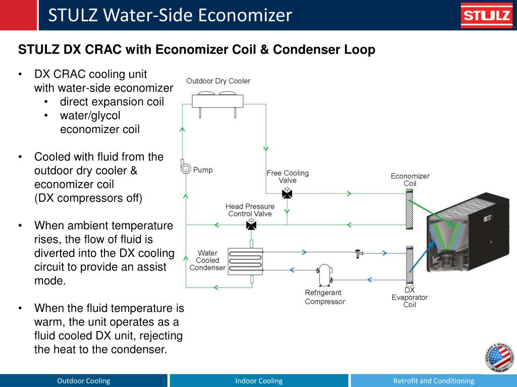
27 Water Side Economizer Diagram - Wiring Database 2020

Carrier Economizer Wiring Diagram

Wiring-Economizer Logic Module
