
Vt Commodore Ignition Wiring Diagram, Complete Wiring Diagrams For Holden Commodore VT, VX, VY, VZ, VE, VF, 5.36 MB, 03:54, 32,796, John Amahle, 2018-08-01T19:37:41.000000Z, 19, Vt Commodore Ignition Wiring Diagram, to-ja-to-ty-to-my-to-nasz-swiat.blogspot.com, 1272 x 1800, jpeg, bcm pcm 12j swiat nasz, 20, vt-commodore-ignition-wiring-diagram, Anime Arts
Astatic does not assume the responsibility of any damage to either the microphone nor any radio that has been modified to the specifications within this manual. Although all have been known to work, the wirings in this manual are only. The following microphone wiring diagrams are for the majority of cb and 10 meter radios available. The world's leading cb radio and radio communication store.
Print the electrical wiring diagram off plus use highlighters to trace the signal. When you employ your finger or perhaps follow the circuit along with your eyes, it may be easy to mistrace the circuit. Schematic diagram (8. 5x11) schematic diagram (11x17) schematic diagram. Factory service manual ( covers 148gtl, 148gtl st, 148 nw st) (dated 1997 1998) page 1 to 15 page 16 to 30 page 31 to 47 page 48 to 63. Different manufacturers may wire their microphones differently. Generally, a radio manufacturer will wire their microphones the same so that the microphones are interchangeable between their radios, however, this is not always the case. For example, cobra 4 pin radios are wired 1) shield 2) audio 3) transmit 4) receive while midland 4 pin radios are wired 1) audio 2) shield 3) receive. Microphone wiring diagrams that show various styles of microphone pin ends and how microphone connections may be different between brands. Cobra 4 pin tx = white, mod = red, rec = blue, shield/common = braid/black.
Whats The Wiring Diagram For A Cobra Hg M77 Cb Mic

Whats The Wiring Diagram For A Cobra Hg M77 Cb Mic
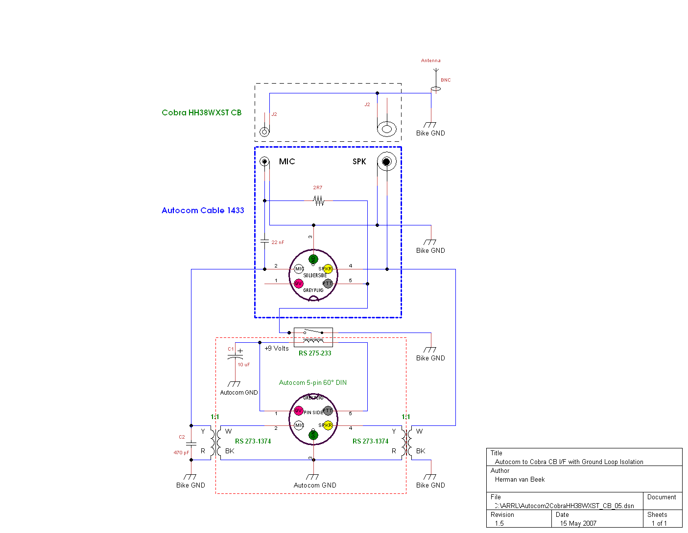
Whats The Wiring Diagram For A Cobra Hg M77 Cb Mic
Whats The Wiring Diagram For A Cobra Hg M77 Cb Mic
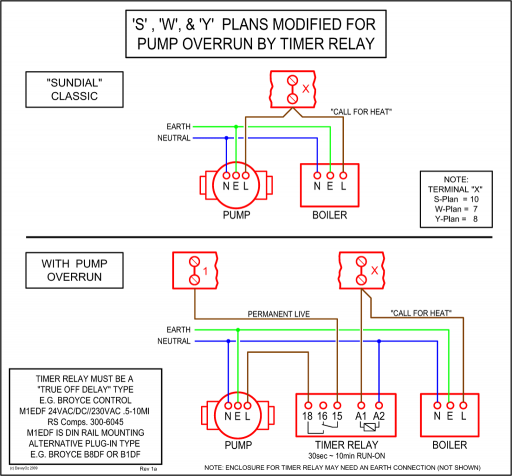
Whats The Wiring Diagram For A Cobra Hg M77 Cb Mic
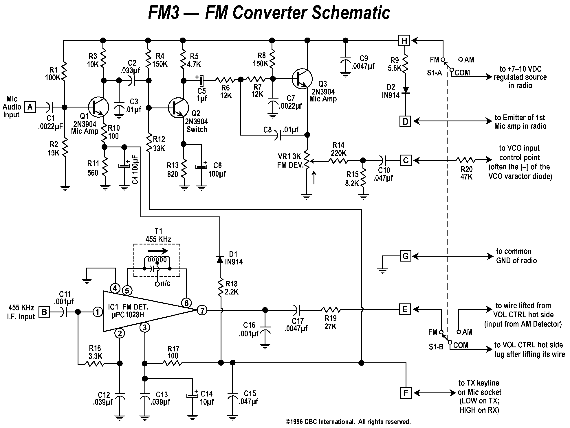
Cobra Cb Mic Wiring Diagram
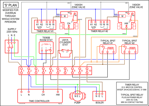
Cobra 4 Pin Mic Wiring
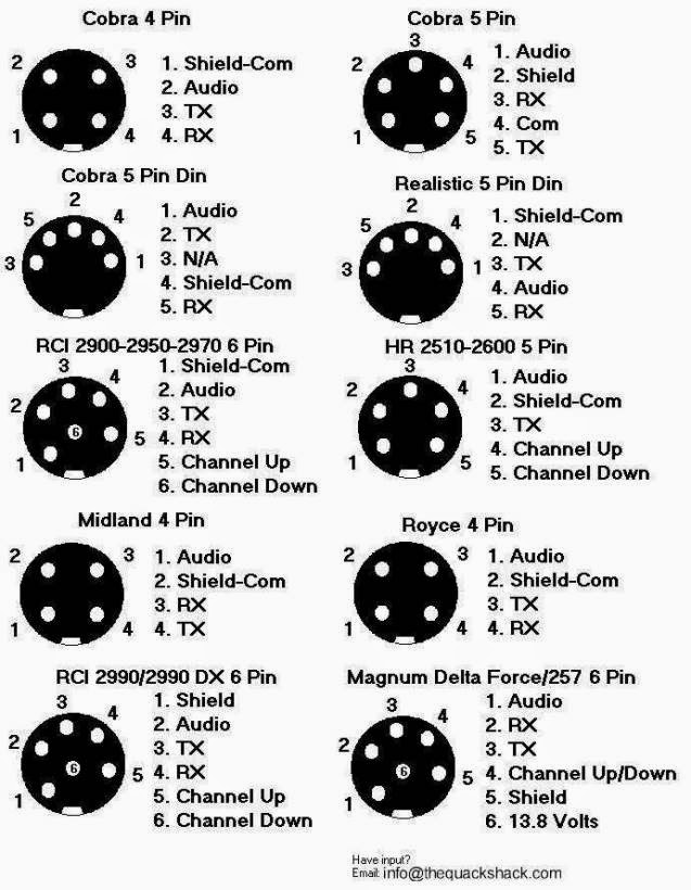
Wiring Diagram For Cobra Cb Mic - Wiring Diagram
Cobra Cb Mic Wiring Diagram
